- Home
- >
- Products
- >
- Powder Pneumatic Conveying System
- >
- Downdraft Bin Pump

Downdraft Bin Pump
Brand :Cafu
Product origin :China
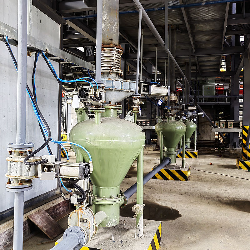
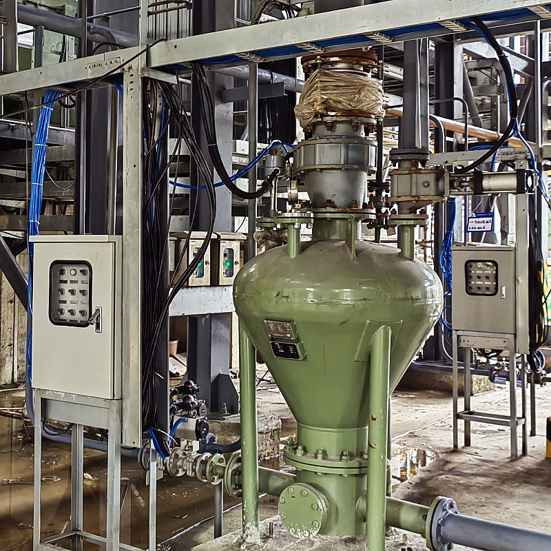
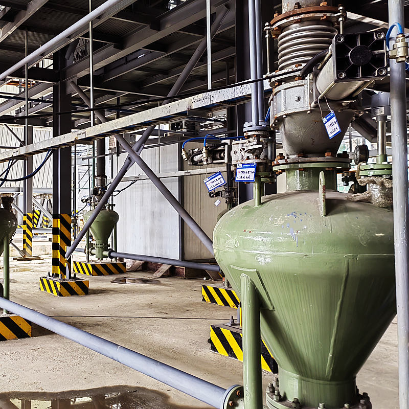
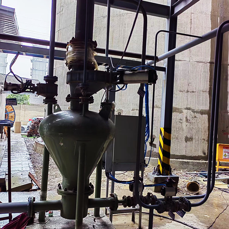
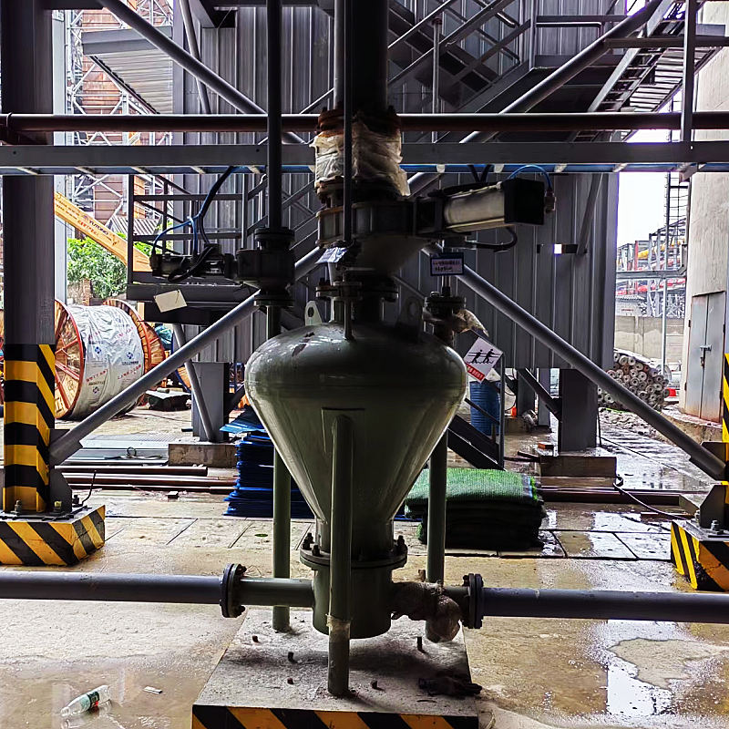
According to the direction of the discharge port, the bin pump is divided into downdraft bin pump, also known as bin pump, pneumatic conveying pump, sending tank, etc. The fluidising plate of the downdraft bin pump is in the lower part of the bin pump, and the fluidising plate is single or double plate. In order to enable the material to be discharged centrally, the conveying pipe is equipped with a conveying valve at the bottom of the bin pump. When the air pressure inside the bin pump reaches a predetermined pressure value, the conveying valve opens and the highly concentrated material flows into the conveying pipe for dense phase conveying.
Process overview of the downdraft bin pump in dense phase conveying systems
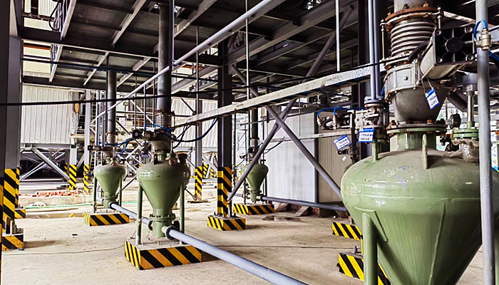
The working process of the downdraft bin pump consists of four major stages that form a working cycle:
▌Feeding stage: the inlet valve and exhaust valve open, the material falls freely into the pump body, when the material is full, the level meter sends a signal, the inlet valve and exhaust valve close automatically, completing the feeding process;
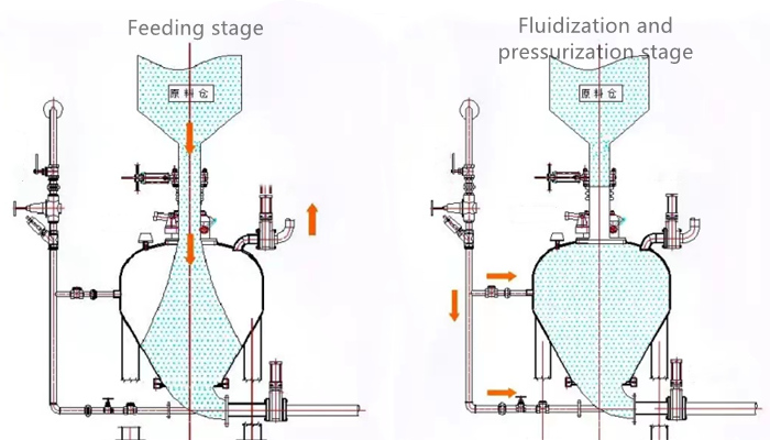
▌Fluidization and pressurization stage: open the inlet valve, compressed air into the upper part of the pump body and the bottom, the upper part of the pressurization, the lower part of the air diffusion through the fluidized bed, so that the material is fluidized, while the pressure in the pump rises;
▌Conveying stage: when the pressure inside the pump reaches a certain value, the pressure gauge or pressure switch sends a signal, the discharge valve opens automatically, the fluidized material on the fluidized bed is fluidized and strengthened, conveying begins, the material inside the pump gradually decreases, at this time the material on the fluidized bed is always in the state of fluidization while conveying;
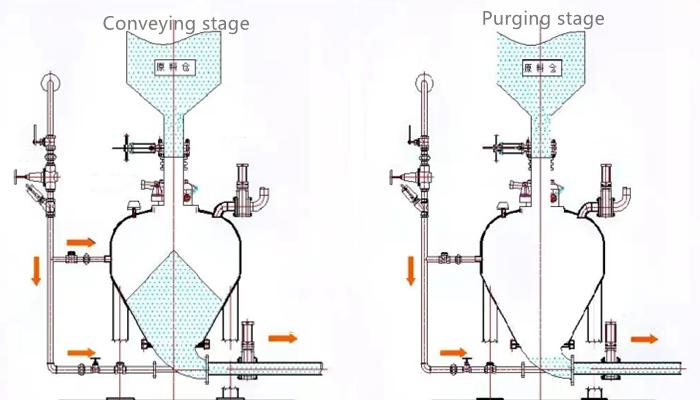
▌Purging stage: when the material in the pump is conveyed, the pressure drops to the pipeline resistance, the pressure gauge or pressure switch issues a signal, the ventilation continues for a certain period of time, the compressed air clears the pipeline, then the inlet valve is closed, and at a certain interval, the discharge valve is closed and the inlet valve is opened to complete a conveying cycle.
The downdraft bin pump used in the dense phase pneumatic conveying system can be divided into carbon steel, stainless steel, etc. according to the material. The surface treatment of the bin pump is sprayed, sandblasted and other processes. CAFU can design a pneumatic conveying system according to the actual needs of customers.
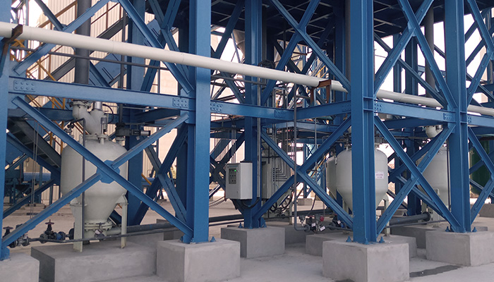
The main features of the pneumatic conveying system include :
▌Environmental protection and energy saving: Due to the reasonable fluidization structure, the material is in a good fluidization state and the gas consumption is reduced. According to the actual situation, after several improvements, the production efficiency has been improved and the energy consumption has been reduced.
▌High ash to gas ratio: good fluidisation effect, low gas consumption and high ash to gas ratio. The actual application shows that the equivalent distance is less than 500 meters, the ash to gas ratio can reach more than 30KG (dry ash)/KG (gas).
▌ Low impact abrasion of materials on pipes: due to low gas consumption and high ash-gas ratio, the flow rate of dry ash materials during transportation is low, the service life of valves and pipes is improved and the service life of system fittings is extended.
The pneumatic conveying system consists of the following main components:
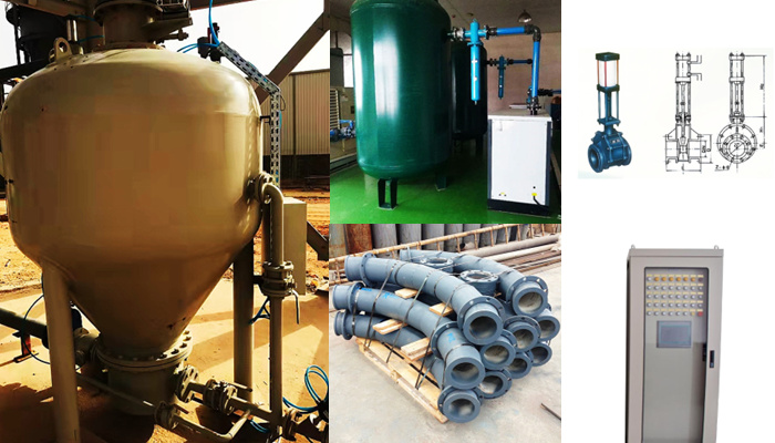
▌Bin pump
▌Conveying pipeline
▌Pipeline valves
▌PLC touch screen control system
It has been proven to be an ideal pneumatic conveying equipment with stable performance, reliable quality and no dust pollution.
▋Downdraft bin pump specification sheet
| Specification | L-0.3 | L-0.6 | L-1.0 | L-1.5 | L-2.5 | L-4.0 | L-6.0 | L-8.0 | |
Effective volume of pump body | m3 | 0.3 | 0.6 | 1.0 | 1.5 | 2.5 | 4.0 | 6.0 | 8.0 |
| Matching piping | mm | 50-80 | 80-100 | 80-100 | 80-125 | 100-125 | 100-150 | 125-175 | 150-175 |
Air consumption | m3/min | 2-3 | 4-5 | 5-8 | 12-16 | 15-18 | 22-30 | 30-36 | 40-50 |
Conveying capacity | t/h | 4 | 8 | 12 | 20 | 25 | 40 | 55 | 70 |
| Total weight | kg | 1000 | 1200 | 2000 | 2400 | 2600 | 3200 | 3600 | 4500 |
| Design max. pressure | Mpa | 0.78 | |||||||
Work Stress | Mpa | 0.1~0.6(Depending on conveying distance) | |||||||
| m | up to 1500 (this value is the converted equivalent length, the conveying capacity decreases as the conveying distance increases) | ||||||||
Operating temperature | ℃ | -20~250, for special products with operating temperature over 120°C, please propose before design. | |||||||
Material | Q235 or 16MnR | ||||||||
※ The conveying capacity and matching parameters in the table are all derived from the actual measured data of transporting fly ash or cement when the equivalent distance is 250m, and are for selection reference only.
Customized design of general fabricated steel silo needs to provide: 1. Storage material name 2. Density of storage material 3. Storage material particle size 4. Storage capacity 5. Feeding method 6. Discharge method and size of discharge port 7. The height of the discharge port from the ground...more

