- Home
- >
- Products
- >
- Powder Pneumatic Conveying System
- >
- Upward Draft Bin Pump

Upward Draft Bin Pump
Brand :Cafu
Product origin :China
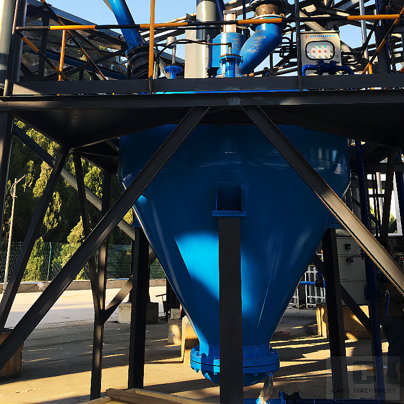
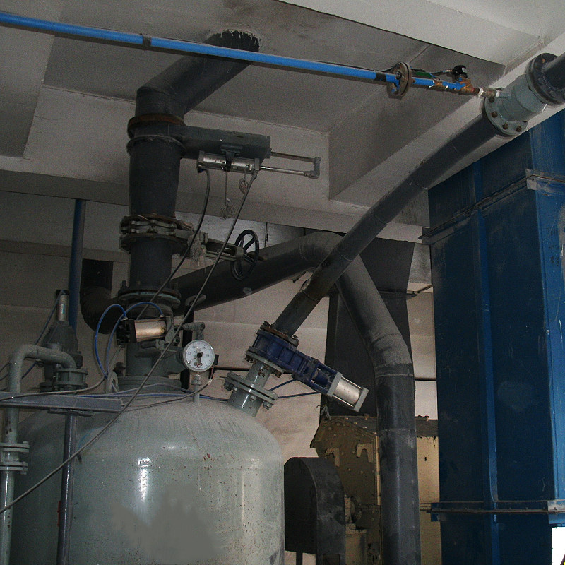
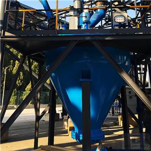
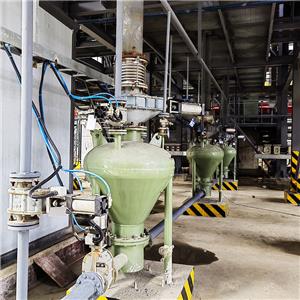
Upward draft bin pump in powder pneumatic conveying system, the fluidising plate is at the bottom of the bin pump, the lower flaring tube of the material delivery pipe is installed at a suitable position above the fluidising plate, the upper end is straight up from the top of the bin pump, the booster jet is installed on the pipe at the outlet.
Upward draft bin pump introduction
▌External schematic
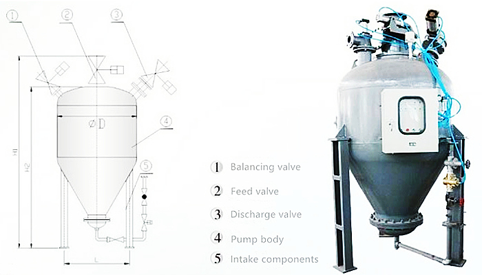
▌Bin pump parameter table
| type | LD1.0 | LD1.5 | LD2.5 | LD4.0 | LD5.0 | LD6.0 | LD8.0 |
| H1(mm) | 3029 | 3126 | 3198 | 3502 | 3849 | 4030 | 4398 |
| H2(mm) | 2389 | 2486 | 2558 | 2862 | 3209 | 3390 | 3758 |
| L(mm) | 560 | 560 | 660 | 660 | 810 | 810 | 1010 |
| D(mm) | 1023 | 1219 | 1623 | 1823 | 1823 | 2023 | 2231 |
▌Description of the bin pump process
Upward draft bin pump for dense phase pneumatic conveying, the fluidised plate is at the bottom of the bin pump, the lower flaring tube of the delivery pipe is installed at a suitable position above the fluidised plate, the upper end is leaded upwards from the top of the bin pump, the booster jet is installed on the pipe at the outlet.
The compressed air enters in a total of three ways:
◇The first way in from the top of the bin pump, so that the back pressure is quickly formed at the top of the pump, pushing the material downwards;
◇The second way is the main air source from the bottom of the bin pump into the fluidised plate and through the gate to regulate the air volume;
◇The third way is from the air pipe into the booster jet, for secondary air replenishment. The size of the supplemental gas flow is adjusted to control the gas to material mixing ratio.
When the pressure in the bin pump reaches a preset value, the delivery valve opens quickly and the highly concentrated gas-mixing stream enters the delivery pipe for smooth pneumatic conveying of the concentrated phase.
▌Composition of the pneumatic conveying system:
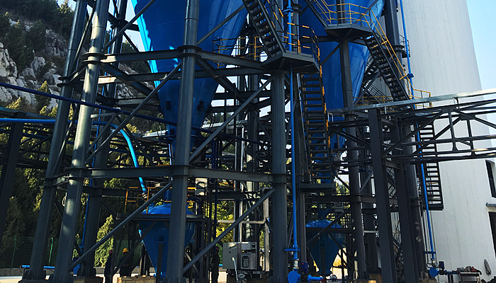
The pneumatic conveying system features and system components of the Upward draft bin pump are close to those of the Downdraft bin pump pneumatic conveying system, see Downdraft bin pump for more information.
▌Upward draft bin pump specification sheet
| Specification | L-0.3 | L-0.6 | L-1.0 | L-1.5 | L-2.5 | L-4.0 | L-6.0 | L-8.0 | |
Effective volume of pump body | m3 | 0.3 | 0.6 | 1.0 | 1.5 | 2.5 | 4.0 | 6.0 | 8.0 |
| Matching piping | mm | 50-80 | 80-100 | 80-100 | 80-125 | 100-125 | 100-150 | 125-175 | 150-175 |
Air consumption | m3/min | 2-3 | 4-5 | 5-8 | 12-16 | 15-18 | 22-30 | 30-36 | 40-50 |
Conveying capacity | t/h | 4 | 8 | 12 | 20 | 25 | 40 | 55 | 70 |
| Total weight | kg | 1000 | 1200 | 2000 | 2400 | 2600 | 3200 | 3600 | 4500 |
| Design max. pressure | Mpa | 0.78 | |||||||
Work Stress | Mpa | 0.1~0.6(Depending on conveying distance) | |||||||
| m | up to 1500 (this value is the converted equivalent length, the conveying capacity decreases as the conveying distance increases) | ||||||||
Operating temperature | ℃ | -20~250, for special products with operating temperature over 120°C, please propose before design. | |||||||
Material | Q235 or 16MnR | ||||||||
▌Upward draft bin pump precautions:
| 1 | The air compressor exhaust pressure should be 1-2kgf/cm2 (0.1-0.2MPa) higher than the operating pressure to ensure that there is still the ability to blow through when blocked |
| 2 | The material to be conveyed must be dry, with a general moisture content of ≤ 5%, so as not to affect the conveyance |
| 3 | Each pipeline shall be subject to gas-tightness test after installation and after long-term discontinuation, before re-use |
| 4 | In operation, there must be a certain delay time after each bin pump material is sent empty to ensure that the pipeline is clean and prevent the pipeline from being blocked, which is especially important in long-term use |
Customized design of general fabricated steel silo needs to provide: 1. Storage material name 2. Density of storage material 3. Storage material particle size 4. Storage capacity 5. Feeding method 6. Discharge method and size of discharge port 7. The height of the discharge port from the ground...more

